- -25%


 Delivery policy
Delivery via Courier
This L298N Motor Driver Module is a high power motor driver module for driving DC and Stepper Motors. This module consists of an L298 motor driver IC and a 78M05 5V regulator. L298N Module can control up to 4 DC motors, or 2 DC motors with directional and speed control.
|
Pin Name |
Description |
|
IN1 & IN2 |
Motor A input pins. Used to control the spinning direction of Motor A |
|
IN3 & IN4 |
Motor B input pins. Used to control the spinning direction of Motor B |
|
ENA |
Enables PWM signal for Motor A |
|
ENB |
Enables PWM signal for Motor B |
|
OUT1 & OUT2 |
Output pins of Motor A |
|
OUT3 & OUT4 |
Output pins of Motor B |
|
12V |
12V input from DC power Source |
|
5V |
Supplies power for the switching logic circuitry inside L298N IC |
|
GND |
Ground pin |
Features & Specifications
The L298N Motor Driver module consists of an L298 Motor Driver IC, 78M05 Voltage Regulator, resistors, capacitor, Power LED, 5V jumper in an integrated circuit.
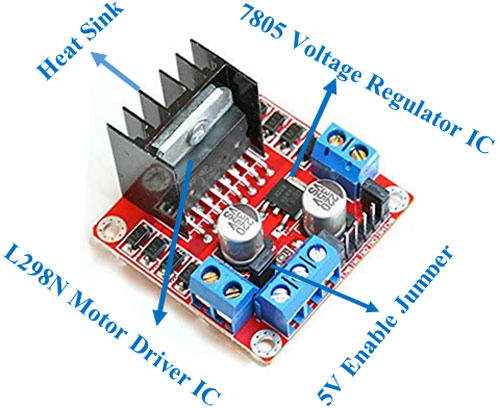
78M05 Voltage regulator will be enabled only when the jumper is placed. When the power supply is less than or equal to 12V, then the internal circuitry will be powered by the voltage regulator and the 5V pin can be used as an output pin to power the microcontroller. The jumper should not be placed when the power supply is greater than 12V and separate 5V should be given through 5V terminal to power the internal circuitry.
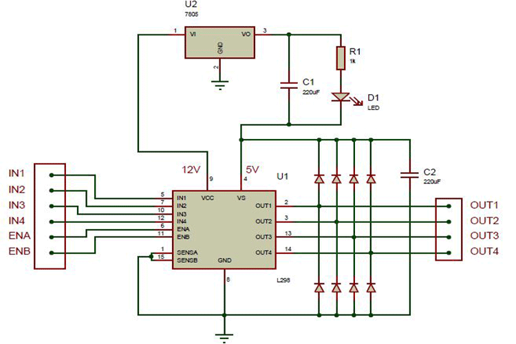
ENA & ENB pins are speed control pins for Motor A and Motor B while IN1& IN2 and IN3 & IN4 are direction control pins for Motor A and Motor B.
Internal circuit diagram of L298N Motor Driver module is given below:
You might also like
Model: MOD-PWR-025
Model: MOD-PWR-024
Model: MOD-PWR-011
Model: MOD-PWR-013


